The cantilevered beam is embedded into a fixed vertical wall at Atext Draw a neat labeled correct free-body diagram of the beam and identify the knowns and the unknowns. The International Building Code IBC and the International Residential code IRC if there are rigid materials such as drywall attached the maximum live load deflection is.

Draw The Moment Diagram For The Cantilevered Beam Draw The Shear Diagram For The Cantilevered Beam Study Com
Assuming that the object that is supporting the shaft is infinitely stiff the above problem can be treated as a cantilever beam.
. Notice that if this. The intensity of the triangular distributed load at the point of sectioning is Referring to Fig. Answer 1 of 8.
Poor quality materials such as chrome-plated zinc instead of stainless steel resulted in fittings decaying all over the boat. James Watt developed the design sporadically from 1763 to 1775 with support from Matthew BoultonWatts design saved so much more fuel compared with earlier designs that they were licensed based. Roarks Formulas for Stress and Strain Formulas for Circular Rings Section 9 Reference loading and load terms 3.
Tip deflection is calculated using Equation 1213. According to current codes widely adopted in the US. The bending moment at G is obviously zero At the supported ends of a simple beam and at the free end of a cantilevered beam where there can 5.
The Watt steam engine alternatively known as the Boulton and Watt steam engine was an early steam engine and was one of the driving forces of the Industrial Revolution. Lightly draw an arc with radius equal to side B. Views of Objects 429 TI P A B B A C C a A photograph shows an object as it appears to the observer but not necessarily as it is.
Enter the email address you signed up with and well email you a reset link. The opinions that you. Draw the shear and moment diagrams for the beams shown below.
Do not draw free-body diagram forces on top of your problem drawing the body needs to be drawn free. Begin by drawing a neat rectangle to represent the beam disconnected from its. It cannot describe the object accurately no.
Loading moment applied M o at θ relative to x angle. Our bay boats agility paired with top-tier fishing amenities create an experience that suits even the most avid of anglers. R 1 20.
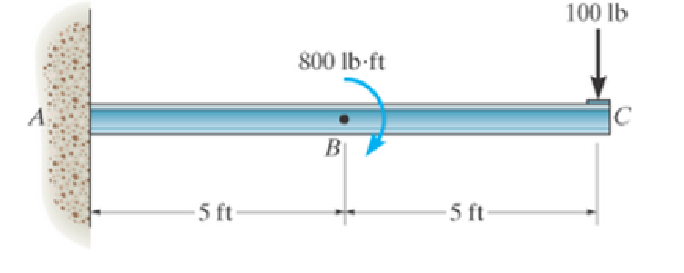
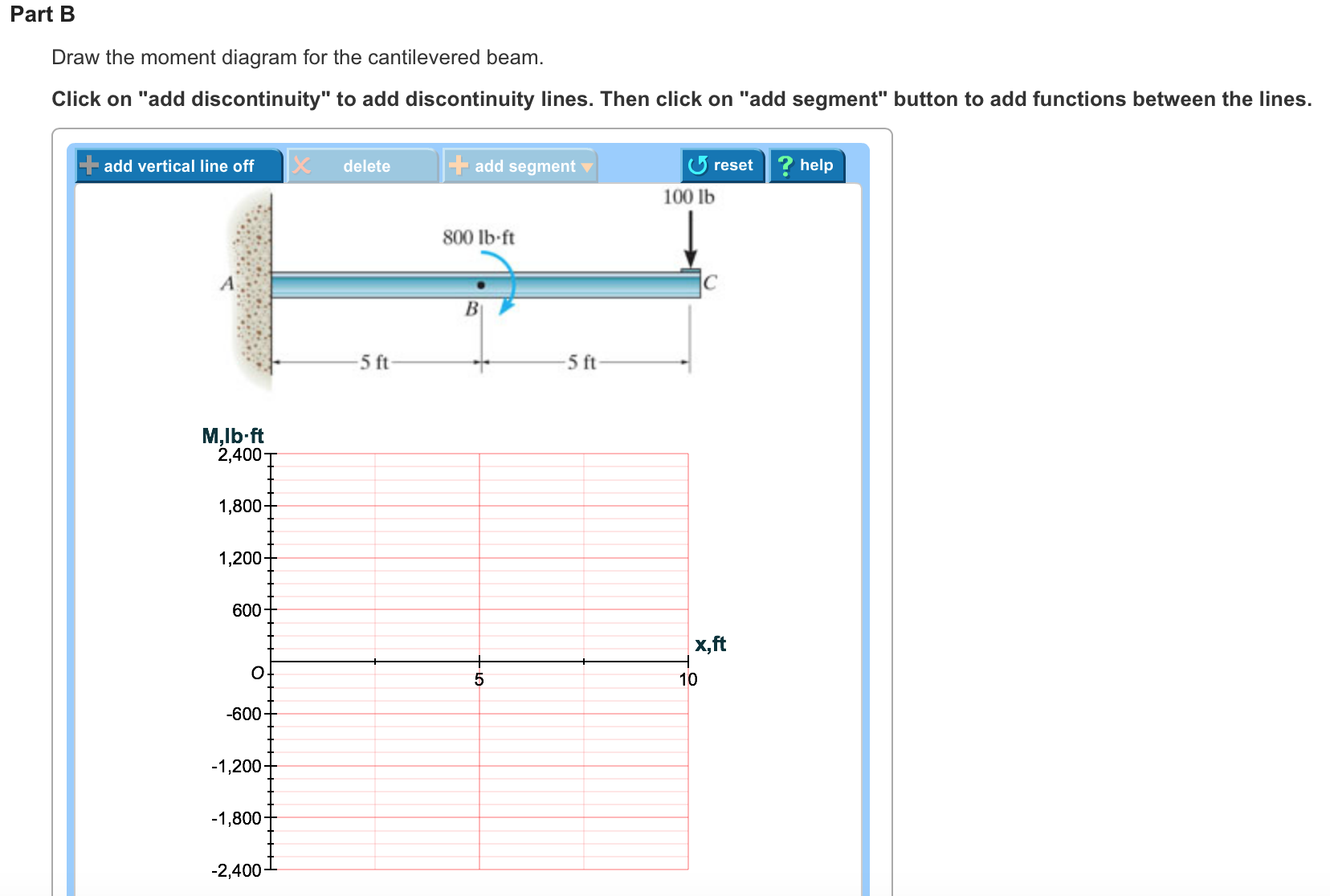
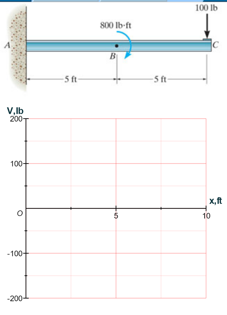
This point gives Forces in pin-jointed frames MH -4 7 512 7 5 30 7 5. Draw the shear and moment diagrams for the cantilevered beam. It contains load estimation I stage steel beam design and II stage composite beam design.
In Figure 1262 a cantilevered beam is anchored at one side and hangs out unsupported. 300 lb 200 lbft A 6 ft The free-body diagram of the beams left segment sectioned through an arbitrary point shown in Fig. B will be used to write the shear and moment equations.
This configuration generates the greatest deflection at the tip and greatest stresses at the anchor. Refer to the image below. At point H we have the maximum bending be no resistance to bending the bending moment moment.
B w 200a x 6 b 3333x The. Draw the shear and moment diagram for the beam shown below and clearly label all values of maximum positive and negative shear and moment. The first step to solving the problem is to draw a free body diagram.
First lets look at the 500 lb weight. From that a free body diagram can be drawn and the shear and moment diagrams can be determined. Draw sides A and B from the intersection of the arcs as shown.
To calculate the stresses and deformations we need the material stiffness E area moment of inertia I applied load M or P and the length L. Permanent Load Gk 38 kNm Variable Load Qk 12 kNm The length of the beam 7. Draw one side as C in the desired position and draw an arc with radius equal to side A.
The bending moment diagrams for the beam and the strain and stress distributions at the mid-span section for the entire range of loading up to full plastification are shown in Figure 2. Email protected Bayliner Trophy Walkaround. Circular Ring Moment Hoop Load and Radial Shear Equations and Calculator 3.
Considering the forces to the right of is always zero. Mechanics of materials solution manual.

Solved 6 12 Draw The Shear And Moment Diagrai Cantilevered Chegg Com

Draw The Shear And Moment Diagrams For The Cantilevered Beam
Draw The Shear And Moment Diagrams For The Cantilevered Beam Prob 7 48 Bartleby

Draw The Shear And Moment Diagrams For The Cantilever Beam Holooly Com
Solved Draw The Moment Diagram For The Cantilevered Beam Chegg Com
Solved Draw The Shear Diagram For The Cantilevered Beam Chegg Com
Solved Problem 7 48 Part A Draw The Shear Diagram For Chegg Com

Draw The Moment Diagram For The Cantilevered Beam Study Com
0 comments
Post a Comment